LTSSM
The slink_ltssm handles the PHY control, training, and lower P state controls. The S-Link LTSSM
is loosely based on the PCIe/USB LTSSM. Some liberties have been taken to reduce complexity and
give a user more flexibilities with regards to link training time.
An overview of the ltssm states as well as the general flow diagram can be seen below

128b/130b Encoding
S-Link supports 128/130b encoding if configured. In this mode, the 128b/130b encoders and decoders are internal to S-Link. This should ease requirements on the SerDes front end. This does mean that additional logic is required in S-Link, so please be aware of this if you are comparing area numbers to other protocols/IPs.
LTSSM States
IDLE
Initial reset state of the link. In this mode, the PHY is completely disabled.
Exit to WAIT_CLK when S-Link is enabled.
WAIT_CLK
Once S-Link is enabled through writing the the PHY CLK will be enabled. Depending on the PHY layer used, the PLL (or other clock source)
should be enabled. The LTSSM will wait for phy_clk_ready to assert. This means that the PHY CLK is active and should
be actively transmitting from Master -> Slave.
Exit to SWITCH after PHY CLK is ready.
SWITCH
This is an intermediate state where the link_clk is switched from the refclk to the phy_clk. At the end of the
switch, the active lanes are enabled. The LTSSM then waits in this state until the TX and RX lanes are ready.
The TX/RX lanes enabled is determined by the active_txs and active_rxs attributes. i.e. if four TX lanes are active
and two RX lanes are active, then phy_tx_en == 'hf and phy_rx_en == 'h3.
Exit to P0_TS1 after all active TX/RX lanes are ready.
P0_TS1
In this state the LTSSM is sending TS1s to the far end. The RX’s are indicated to begin byte/symbol alignment using the TS1/2 sets. The RX Deskew FIFO is enabled to remove any lane-to-lane skew.
The TS1s are actually recognized in the RX Deskew FIFO. The deskew logic observe for each byte of the TS1 to be correct then assert a TS1 indication to the LTSSM, incrementing the TS1 counter.
Exit to P0_TS2 once
ts1_tx_countTS1 are sent ANDts1_rx_countTS1 are seen, OR if any TS2s are seen.
P0_TS2
Similar to P0_TS1 state except that we are sending TS2s.
Exit to P0_SDS once
ts2_tx_countTS1 are sent AND ts2_rx_count` TS1 are seen, OR if the SDS is seen.
Note
The number of TSx sets required can be changed based on the P State that is being exited. This is done through the S-Link Attributes.
P0_SDS
This is a state in which the SDS is sent to the far end. After the SDS is sent, the link is considered up and starts to send packet data.
Exit to P0 after sending SDS.
P0
This is the main data sending state.
Exit to ATTR_ST when there is a far end attribute to update and the LL_TX is idle
Exit to PX_REQ_ST when PX request condition is seen and the LL_TX is idle
Exit to RESET when reset condition is seen
ATTR_ST
When far end S-Link Attributes are to be updated, this state is entered to send an Attribute OS. This state is only entered when the link layer is not actively transmitting data. Because of this, there may be a delay between issuing the attribute command and it being executed. A user should take this into consideration when programming far end attributes.
Local attribute programming does not force the LTSSM into this state.
Exit to P0 after sending the Attribute OS.
Note
If multiple Attribute OS’s are scheduled, the link will still transition back to P0 after each one.
PX_REQ_ST
When the user wishes to enter a lower power state (see Power State Handshake), the LTSSM transitions to PX_REQ_ST to start sending the respective P-Req OS’s. This continues until the appropriate P-Req response is seen.
Exit to PX_START_ST after Px Req OS has been received
PX_START_ST
After Px Request OS’s have been sent and received, the LTSSM will transition to PX_START_ST. Here, the LTSSM will send a PStart OS and transition to the P0_EXIT.
Exit to P0_EXIT after sending PStart OS
P0_EXIT
P0_EXIT is a small state in which the lanes remain active to ensure all data has been pushed through the link and/or PHY.
Exit to respective P1/P2/P3 state based on earlier request.
P1
P1 state is a lower power state in which the TX/RX lanes are disabled for power savings. It is expected that a user would try to enter P1 as much and often as possible to save power.
Exit to P0_TS1 when wake condition is seen.
P2
P2 state is a low power state in which, the TX/RX lanes are disabled and the data rate clock from the Master is disabled. The clock source in the master (PLL or other logic) should remain active to ensure P2 exit is short.
Exit to WAIT_CLK when wake condition is seen.
P3
P3 state is a low power state in which the TX/RX lanes are disabled as well as the data rate clock from the Master. P3 is similar to P2 with the exception that in P3 the master is allowed to completely disable the clock source (PLL or other clock source) for additional power savings. From the slave perspective, there is no real difference between P2 and P3, except that it is understood that a longer exit latency is expected when exiting.
Exit to WAIT_CLK when wake condition is seen.
RESET
The RESET state is reachable by all other states and is entered when a reset request is seen from either side of the link. A local reset request happens either by software intervention and/or through some link condition that warrents a reset (ECC/CRC corruption). Link conditions that warrant a reset can be configured by the ERROR_CONTROL software register.
Exit to IDLE when reset condition is no longer valid. A wake condition will not take precedence over a reset condition.
Note
Inside the S-Link RTL there are additional transition states. These are not listed here for clarity.
Note
Plan to add in a training timeout. Still deciding if we will make the link perform a Reset Condition or if it will just try to go back to P0_TS1. Thinking a Reset Condition since P0_TS1 is pretty much the starting point anyways.
Internal Ordered Sets
For communicating between both sides of S-Link, internal ordered sets are used. These are similar to PCIe/USB (when in 128/13x encoding), although some addtional OS’s have been implemented and some are not used.
SYNC
SYNC ordered sets are the same as USB SYNC’s and PCIe EIEOS. They are used by the BlockAligner to acquire block alignment with the start of block and sync headers. They are only sent during the P0_TS1 and P0_TS2 LTSSM states. The attribute SYNC_FREQ (S-Link Attributes) is used to set the frequency of how often the SYNC OS’s are sent.
Byte |
Value |
Description |
|---|---|---|
0,2,4,8,
|
0x00 |
|
10,12,14
|
0xFF |
Note
SYNC/EIEOS in USB/PCIe are used for signal detection logic. S-Link has no requirements on signal detection since sideband signals are used to indicate start of data. However, a user is free to implement features to detect this for additional enhancements.
TS1
TS1’s are the beginning training set that are sent during the :ref:`P0_TS1’ LTSSM state.
Byte |
Value |
Description |
|---|---|---|
0 |
0x1E |
TS1 OS Identifier |
1-15 |
0x55 |
TS1 Filler |
TS2
TS2’s are the second training set that are sent during the :ref:`P0_TS1’ LTSSM state.
Byte |
Value |
Description |
|---|---|---|
0 |
0x2D |
TS2 OS Identifier |
1-15 |
0xAA |
TS2 Filler |
Note
In the future, S-Link may utilize TS1/TS2 bytes 1-15 for link related attributes or settings.
SDS
Byte |
Value |
Description |
|---|---|---|
0 |
0xe1 |
SDS OS Identifer |
1-15 |
0xAB |
SDS Filler |
P-Req
P1 Req
Byte |
Value |
Description |
|---|---|---|
0 |
0xd1 |
P1 Req Identifier |
1-15 |
0x76 |
Px Req Filler |
P2 Req
Byte |
Value |
Description |
|---|---|---|
0 |
0xd2 |
P2 Req Identifier |
1-15 |
0x76 |
Px Req Filler |
P3 Req
Byte |
Value |
Description |
|---|---|---|
0 |
0xd3 |
P3 Req Identifier |
1-15 |
0x76 |
Px Req Filler |
PStart
Byte |
Value |
Description |
|---|---|---|
0 |
0xd8 |
PStart Identifier |
1-15 |
0x76 |
Px Req Filler |
Attribute OS
Attribute WRITE
Byte |
Value |
Description |
|---|---|---|
0 |
0xa1 |
Attribute Write Identifier |
1 |
addr[7:0] |
Lower byte of attribute address |
2 |
addr[15:8] |
Upper byte of attribute address |
3 |
data[7:0] |
Lower byte of attribute write data |
4 |
data[15:8] |
Upper byte of attribute write data |
5-15 |
0x17 |
Filler |
Attribute READ
Byte |
Value |
Description |
|---|---|---|
0 |
0xa0 |
Attribute Read Identifier |
1 |
addr[7:0] |
Lower byte of attribute address |
2 |
addr[15:8] |
Upper byte of attribute address |
3-15 |
0x17 |
Filler |
Power State Handshake
There are two ways in which a user can place S-Link into a lower power state; through hardware or software. For hardware, the user would assert the p1_req, p2_req,
or p3_req signals. For software, the user would write the PSTATE_CONTROL register with the respective bitfield. For both hardware and software methods, if
more than one P state is requested (e.g. you have p1_req and p2_req asserted) the lowest power state is taken (P2 in this example).
When a P State Request is seen, S-Link will continue to send any packet currently in flight, then, provided another packet does not need to start via tx_sop being asserted,
S-Link will start to send P state request OS’s to the far side S-Link. The far-side will see these packets, and once it has finished sending any packets in-flight and it
is not being requested to send another packet via it’s tx_sop being asserted, it will proceed to begin sending P state request OS’s, mirroring the P State Request.
Once the request packets have been seen and sent on both sides of the S-Link, both sides will send a P State Start OS and the LTSSM for each S-Link controller will move to the requested power state.
Note
Currently there is no way for either S-Link controller to “reject” a power state request. I did think about adding this but came up with a few conclusions:
Generally from a chiplet perspective one side is handling the majority of the traffic handling and therefore would know it’s acceptable to go into a lower power state, deciding the state based on the system wide requirements of exit latency and preferred power savings. Just making both sides force the acceptance simplified the handshake and need to check to see if the power state was accepted.
I wasn’t sure exactly how this would/should be implemented and so I took a simple approach to get going and will make changes once more use cases pop up.
P State Exit is handled by a wake request, reset condition, or if a packet at either end is set to be sent by tx_sop assertion.
Note
A somewhat neat feature can be exploited with regards to power states. If a user wants their link to always be attempting a lower power state, they
can keep p[1|2|3]_req asserted at all times and when they wish to send packets, just send packets as required. This does incur an exit latency
but can keep the user from having to create logic to constantly wakeup and sleep the link.
Reset / Wake Sideband Signals
Protocols have implemented various different methods for signaling specific line state conditions to reset or wake up a link. Electrical Idle, LFPS, DIF-P/N/Z, DPHY LP States, etc. These methods generally require additional analog logic to sense the line state and take appropriate action. This also causes additional logic in the PCS/controller to handle such situations. S-Link decided to take a simpler approach in which we have two additional sideband signals:
slink_reset_nslink_wake_n
Both signals are active low. Both sides of the S-Link share the same bump. When not asserted, a soft pullup should be used to keep each signal high.
Reset Condition
A reset condition occurs any time that slink_reset_n is asserted. When the reset condition is seen, the LTSSM starts the transition to the RESET state
as described above.
Hard Reset Condition
A Hard Reset occurs when a reset condition (slink_reset_n asserted) for 100us+. During a hard reset, the attributes are reset to the original default values.
Note
The hard reset detect time can be set based on the hard_reset_us attribute.
Warning
Currently the hard_reset_us attribute will reset to the default of 100us if a hard reset is seen. A future version of S-Link may allow
the hard_reset_us attribute to remain unaffected by the hard reset condition.
Wake Condition
slink_wake_n is asserted anytime one side of the link wishes to send data and it is not in P0 state. The master or slave can assert
slink_wake_n and the other side is required to respond to the request.
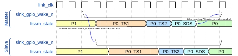
slink_wake_n is deasserted anytime the link is in P0 or if the link is in a low power state and has no data to send (state P1 in the example above). When
data is requested to be sent the S-Link controller that is initiating the wake request will assert the slink_wake_n line. The other S-Link will see this request
and, begin the exit from it’s lower power state, and both sides will begin link training.
Upon finishing link training (entering P0), both S-Link controllers will deassert slink_wake_n. While in P0, the S-Link controller will ignore slink_wake_n as it
is already conceptually woken up.